Solutions
Products
-
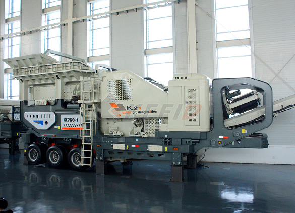
Primary mobile crushing plant
-
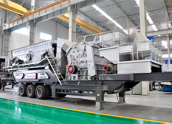
Independent operating combined mobile crushing station
-
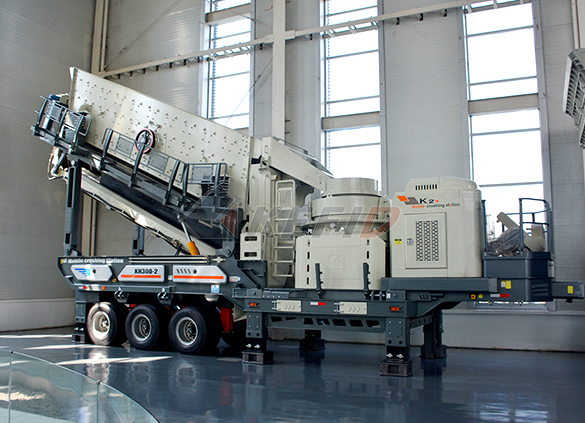
Mobile secondary crushing plant
-
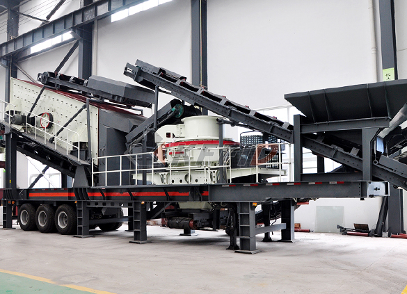
Fine crushing and screening mobile station
-
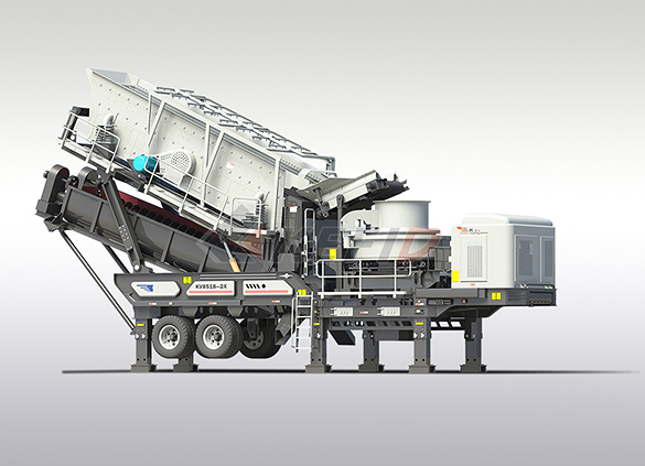
Fine crushing & washing mobile station
-
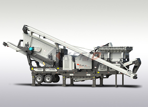
Three combinations mobile crushing plant
-
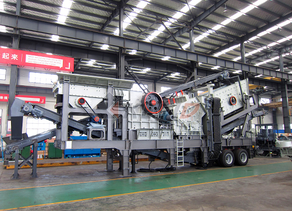
Four combinations mobile crushing plant
-
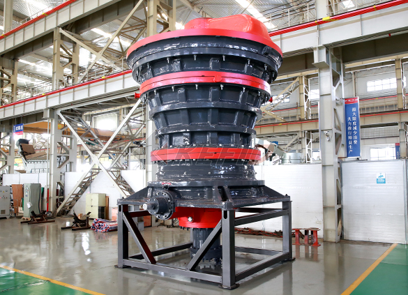
HGT gyratory crusher
-
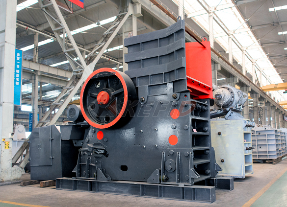
C6X series jaw crusher
-
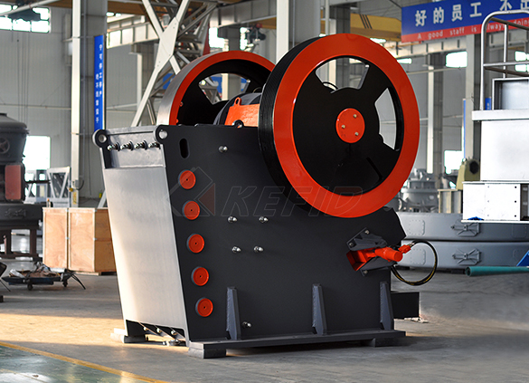
JC series jaw crusher
-
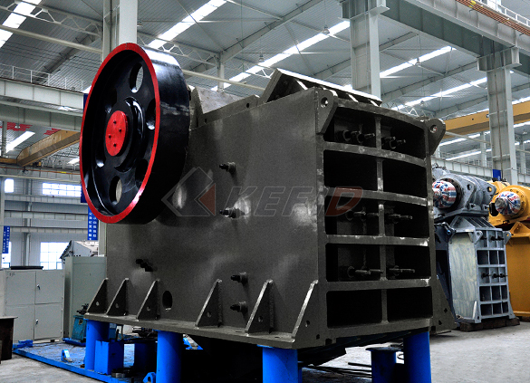
Jaw crusher
-
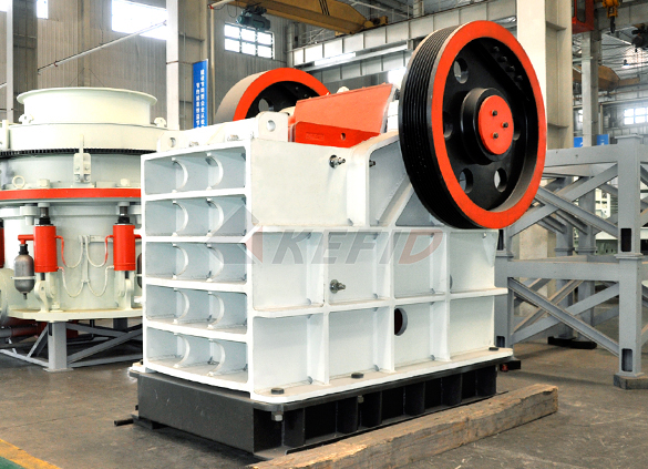
HJ series jaw crusher
-
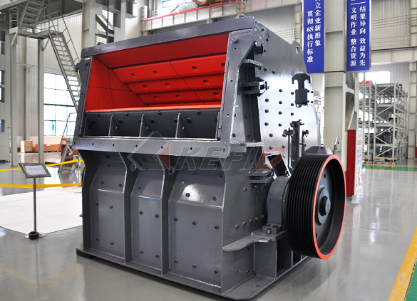
CI5X series impact crusher
-
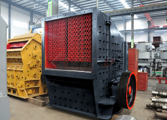
Primary impact crusher
-
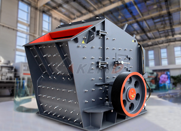
Secondary impact crusher
-
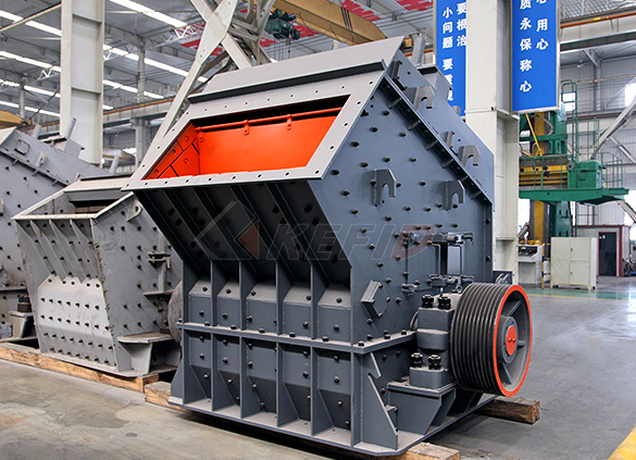
Impact crusher
-
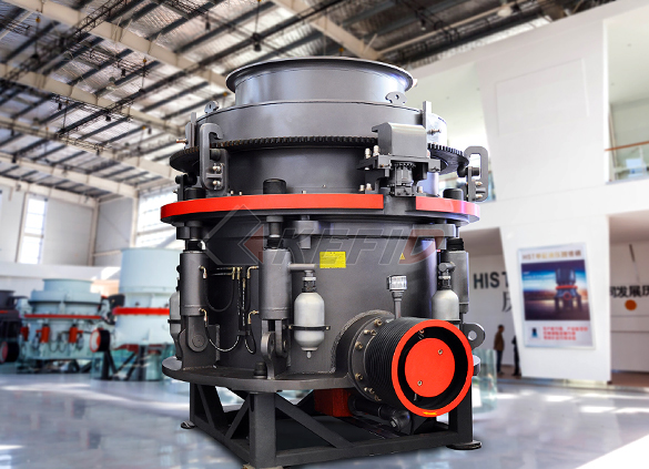
HPT series hydraulic cone crusher
-
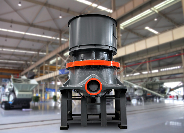
HST hydraulic cone crusher
-
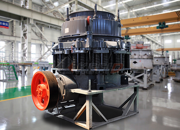
CS cone crusher
-
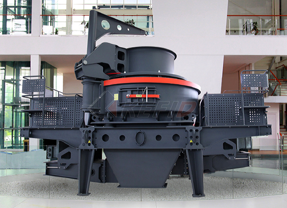
VSI6S vertical shaft impact crusher
-
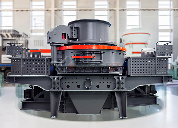
Deep rotor vsi crusher
-
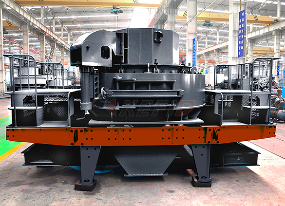
B series vsi crusher
-
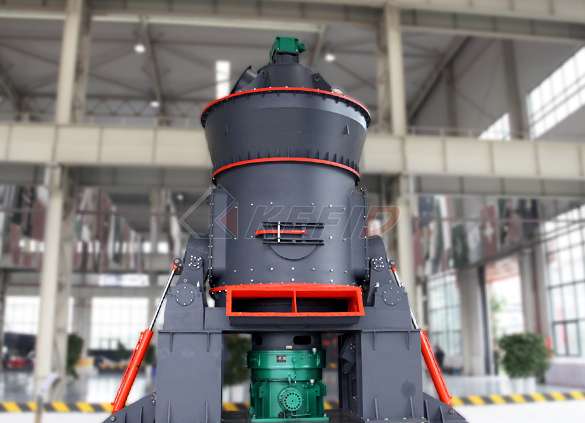
Vertical grinding mill
-
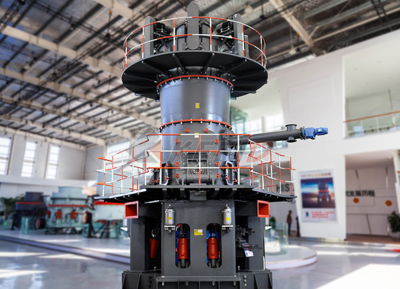
Ultra fine vertical grinding mill
-
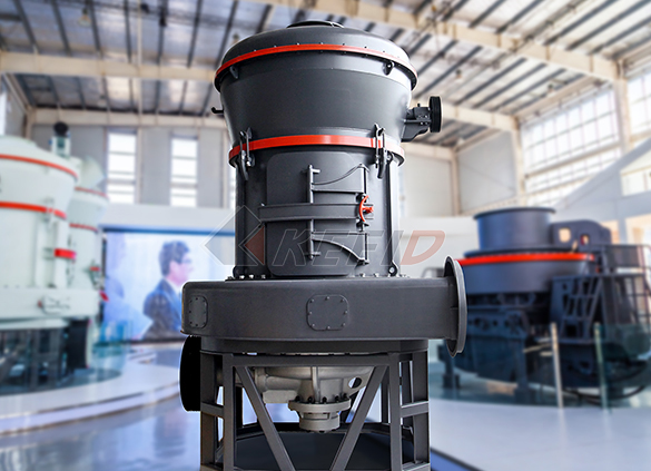
MTW european grinding mill
-
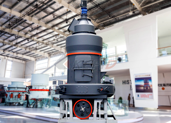
MB5X158 pendulum suspension grinding mill
-
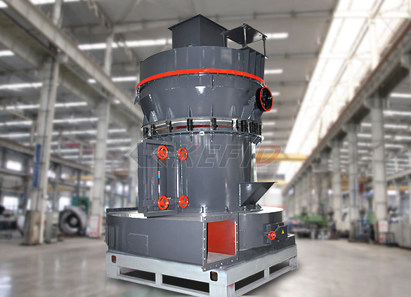
Trapezium mill
-
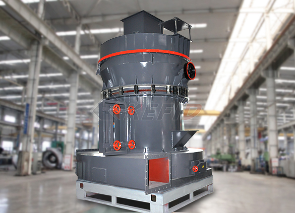
T130X super-fine grinding mill
-
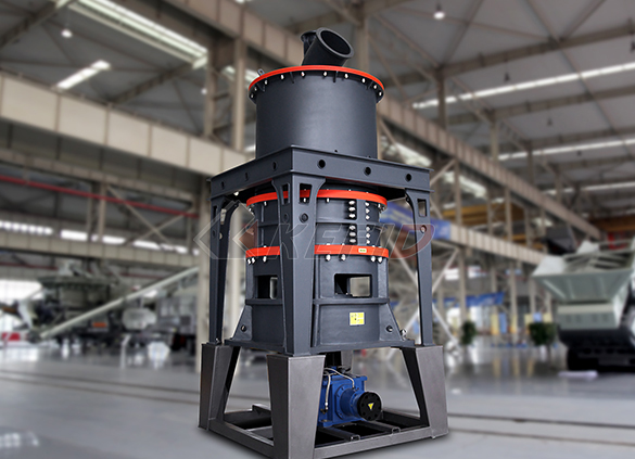
Micro powder mill
-
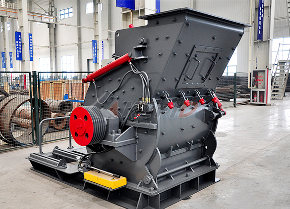
European hammer mill
-
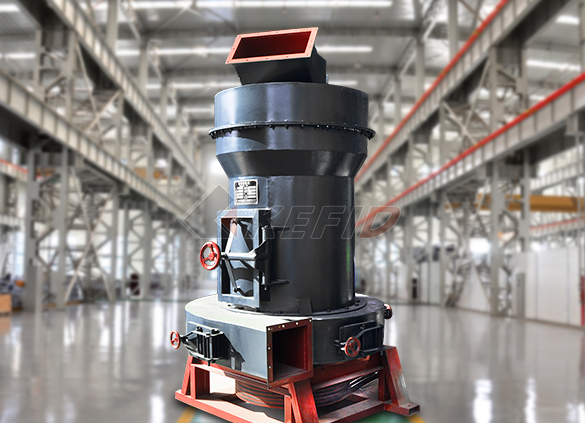
Raymond mill
-
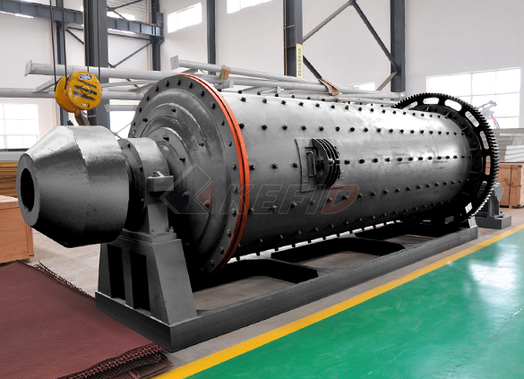
Ball mill
-
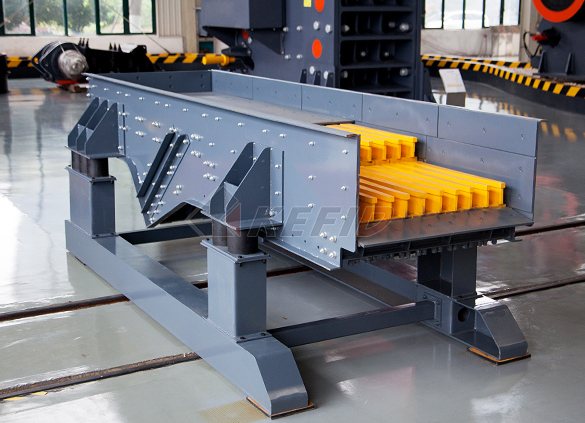
GF series feeder
-
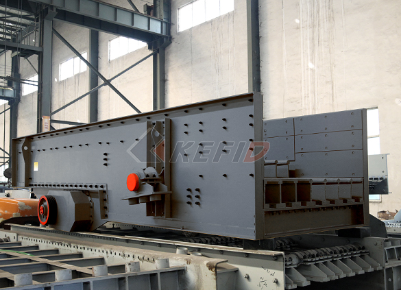
FH heavy vibrating feeder
-
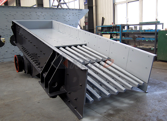
TSW series vibrating feeder
-
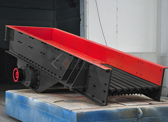
Vibrating feeder
-
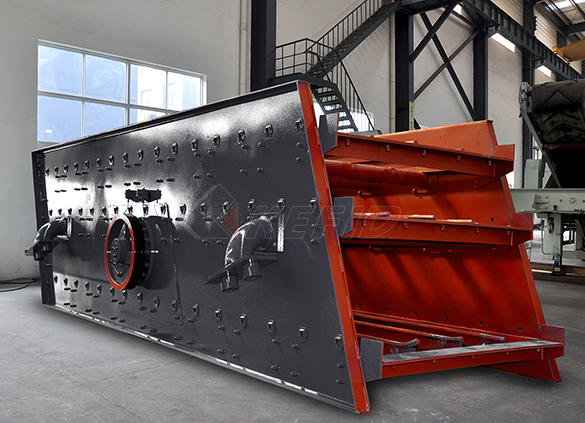
Vibrating screen
-
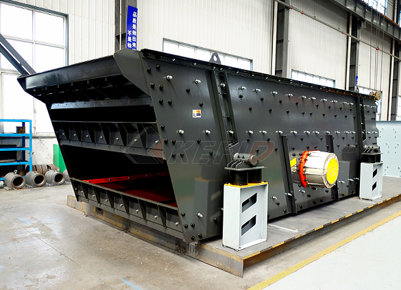
S5X vibrating screen
-
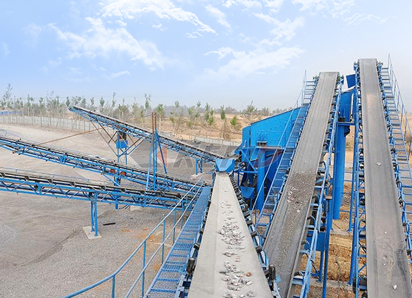
Belt conveyor
-
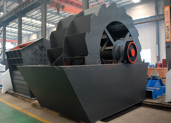
Wheel sand washing machine
-
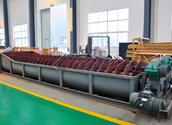
Screw sand washing machine
-
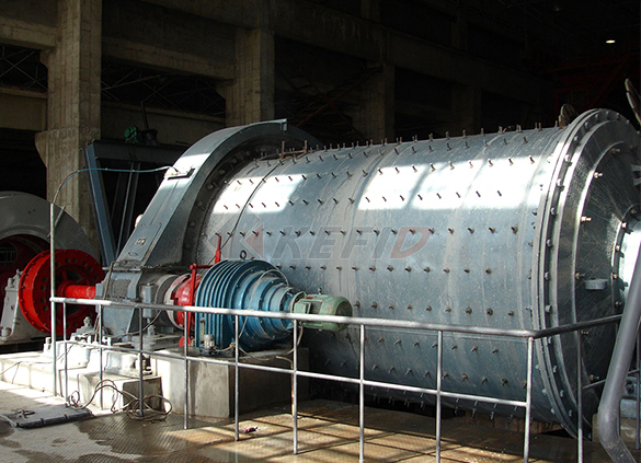
Rod mill
-
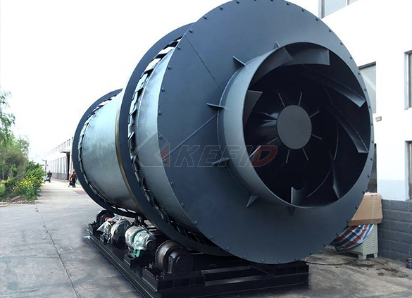
Dryer
-
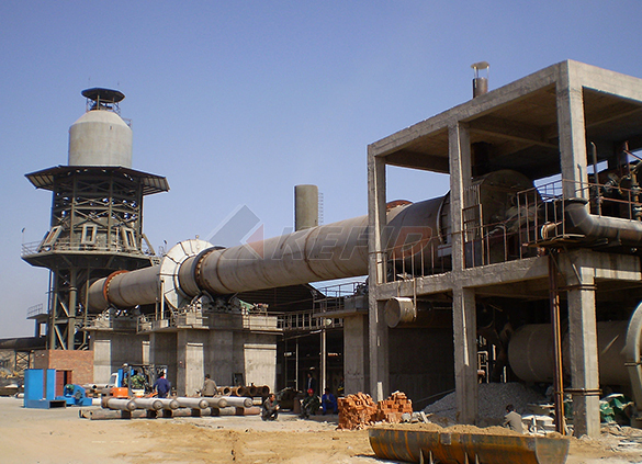
Rotary kiln
-
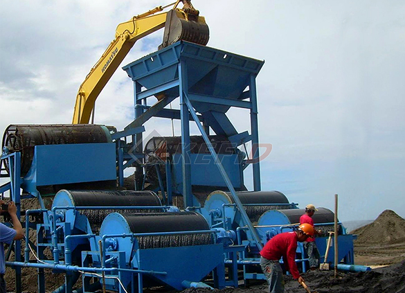
Wet magnetic separator
-
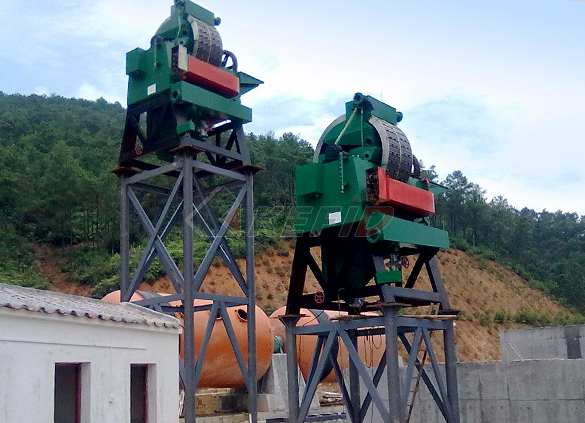
High gradient magnetic separator
-
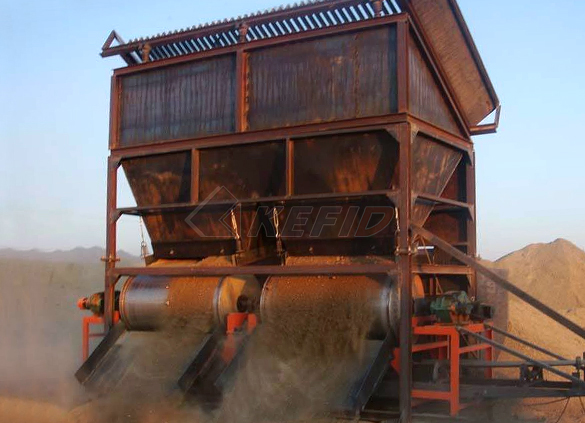
Dry magnetic separator
-
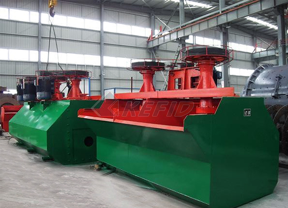
Flotation machine
-
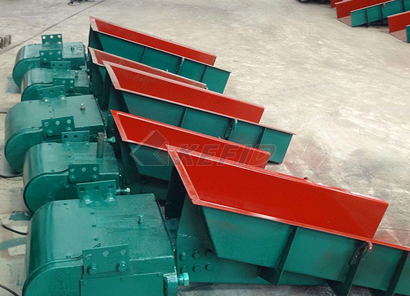
Electromagnetic vibrating feeder
-
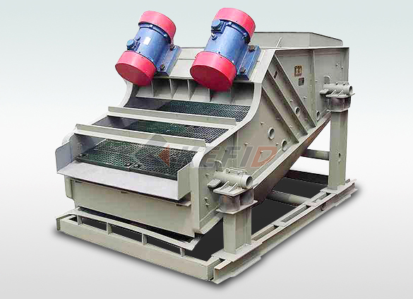
High frequency screen
AS 14032004 Design of rotating steel shafts
Design of rotating steel shafts 1 SCOPE This Standard provides formulae for the design of rotating steel shafts that are subjected to torsional, bending and axialtensile loads either singly or in combination, on the basis of infinite life The Standard does not cover specially developed shafts, for example, those involvingJun 17, 2020 AS1403 is the current Australian standard used in the design of rotating steel shafts The rationale behind AS1403 is to design the shaft for an infinite fatigue life under the applied operating loads, utilising an appropriate safety factorDesign of Rotating Steel Shafts for Mobile Equipment on a rotating shaft, as a specific stress element will alternate from compression to tension in every revolution of the shaft The normal stress due to bending moments will be greatest on the outer surfaces In situations where a bearing is located at the end of the shaft, stresses near the bearing are often not critical since the bendingDesign of Shafts IIT Bombay

Rotating Steel Shafts Strength Of Materials Fatigue
DESIGN FOR FATIGUE AS1403 is the current Australian standard used in the design of rotating steel shafts There are a number of similar international standards including the Question 2 2A Figure Q2A shows two gears A and C attached to a shaft supported by bearing and B and D Forces acted on gear A and C are 180 N and 200 N respectively Draw load, shear force, bending moment and shaft torsional moment diagrams for the shaft, in both XY and XZ planes, and then locate the most endangered xsection of the shaftSAAHB6: Design Of Rotating Steel Shafts Mechanical Jul 19, 2017 Design of Shaft • A shaft is a rotating member usually of circular crosssection (solid or hollow), which transmits power and rotational motionUnit 2 design of shaft SlideShare

Machine Design: LESSON 14 DESIGN OF SHAFTS
1435 Design of Shaft on the basis of Rigidity 14351 Torsional Rigidity For a shaft subjected twisting moment, the angle of twist is given by, Where, T = Torqe applied L = Length of the shaft J = Polar moment of inertia of the shaft about the axis of rotationIntroduction to the Shaft: • A shaft is a rotating member, usually of circular cross section, used to transmit power or motion • It provides the axis of rotation, or oscillation, of elements such as gears, pulleys, flywheels, cranks, sprockets, and the like and controls the geometry of their motionShaft Design Material , Types , How to Design ShaftShaft design based on strengthShaft design based on strength ASME design code: Combined shock and fatigue factorsCombined shock and fatigue factors Type of load Stationary shaft Rotating shaft Type of load km kt km kt Gradualy applied load 1 1 15 1 Suddenly applied load, minor shock 152 Mechanical Design
Course name : Design of Macine Elements1
material properties However, the above equation is further standarised for steel shafting in terms of allowable design stress and load factors in ASME design code for shaft 816 ASME design Code The shafts are normally acted upon by gradual and sudden loads Hence, the equation (817) is modified in ASME code by suitable load factors, 2 2 0 2Question 2 2A Figure Q2A shows two gears A and C attached to a shaft supported by bearing and B and D Forces acted on gear A and C are 180 N and 200 N respectively Draw load, shear force, bending moment and shaft torsional moment diagrams for the shaft, in both XY and XZ planes, and then locate the most endangered xsection of the shaftSAAHB6: Design Of Rotating Steel Shafts Mechanical Jul 19, 2017 Design of rotating shafts and fatigue consideration The most generalized situation the rotating shaft may have both steady and cyclic components of bending stress (σav,σr) and torsional stress (τav,τr) The most frequently encountered stress situation for a rotating shaft is to have completely reversed bending and steady torsional stressUnit 2 design of shaft SlideShare

Machine Design: LESSON 14 DESIGN OF SHAFTS
1435 Design of Shaft on the basis of Rigidity 14351 Torsional Rigidity For a shaft subjected twisting moment, the angle of twist is given by, Where, T = Torqe applied L = Length of the shaft J = Polar moment of inertia of the shaft about the axis of rotationShaft design based on strengthShaft design based on strength ASME design code: Combined shock and fatigue factorsCombined shock and fatigue factors Type of load Stationary shaft Rotating shaft Type of load km kt km kt Gradualy applied load 1 1 15 1 Suddenly applied load, minor shock 152 Mechanical Design1 August 15, 2007 1 17 Shaft Design Objectives • Compute forces acting on shafts from gears, pulleys, and sprockets • Find bending moments from gears, pulleys, or sprockets that are transmitting loads to or from other devices • Determine torque in shafts from gears, pulleys, sprockets, clutches, and couplings • Compare combined stresses to suitable allowable stresses,Md17 Shaft Design

UNIT 7 SHAFTS Shafts IGNOU
rotating parts like gears and pulleys and in turn are themselves supported by bearings design couplings for shafts 72 TYPES OF SHAFT The types of shaft are mentioned in introduction Figure 71(a) shows a stepped shaft Shafts could be made in mild steelSep 30, 2015 Shaft Design for Stress At a machined shaft shoulder the small diameter d is 28 mm, the large diameter D is 42 mm, and the fillet radius is 28 mm The bending moment is 1424 Nm and the steady torsion moment is 1243 Nm The heattreated steel shaft has an ultimate strength of 𝑆 𝑢𝑡 =735 MPa and a yield strength of 𝑆 𝑦 = 574 MPaShafts and Shafts Components SlideShareMay 19, 2009 Hi all, I'm trying to design a rotating shaft for a large piece of machinery It is supported by two bearings with a scoop mounted to the middle of the shaft between the bearings The scoop is perpendicular to the shaft so that as the shaft rotates the scoop sweeps material awayDesign of rotating shaft with axial load Mechanical

(PDF) Problem Set 8 Chapter 17 Shafts Selected Problems
2 The book, Mechanical Details for Product Design, edited by Douglas C Greenwood, McGrawHill, Inc, 1964, p 288291, illustrates typical methods of coupling rotating shafts Methods of coupling rotating shafts vary from simple bolted flange constructions to complex spring and synthetic rubber mechanismsRotating steel shafts are typically one of the most critical mechanical components on mobile equipment This article talks about some general principles of good shaft design and issues to be aware of April 6, 2020 Transfer Chute Analysis with Discrete Element and Continuum Modellingaspecau Aspec EngineeringThe turbine is the heart of MTs because it plays the main role in electric power production and in singleshaft design, where a compressor and a generator are rotating with the turbine A turbine is a rotary mechanical device, which is used to convert the energy of a working fluid to useful workShaft Design an overview ScienceDirect Topics

49 Design of Rotating Steel Shafts AS 1403 2004 50 Steel
49 Design of Rotating Steel Shafts AS 1403 2004 50 Steel Structures AS 4100 from ENG 102 at UET TaxilaThe design of rotating steel shafts is a classical mechanical engineering problem Since the recognition of fatigue as a major source of failures in shafts, many different criteria for fatigue design of rotating steel shafts have been put forward Two commonly used approaches are based on the Soderberg criterion and on the DIN 743 approachA comparison of methodologies for fatigue analysis of Design of Rotating Steel Shafts: AS 14032004 : Australian Standard Standards Association of Australia, Standards Australia International Limited Standards Australia, 2004 Conveying machinery 50 pages 0 Reviews What people are saying Write a Design of Rotating Steel Shafts: AS 14032004 : Australian

Machine Design: LESSON 14 DESIGN OF SHAFTS
1435 Design of Shaft on the basis of Rigidity 14351 Torsional Rigidity For a shaft subjected twisting moment, the angle of twist is given by, Where, T = Torqe applied L = Length of the shaft J = Polar moment of inertia of the shaft about the axis of rotation1 August 15, 2007 1 17 Shaft Design Objectives • Compute forces acting on shafts from gears, pulleys, and sprockets • Find bending moments from gears, pulleys, or sprockets that are transmitting loads to or from other devices • Determine torque in shafts Md17 Shaft Designrotating parts like gears and pulleys and in turn are themselves supported by bearings design couplings for shafts 72 TYPES OF SHAFT The types of shaft are mentioned in introduction Figure 71(a) shows a stepped shaft Shafts could be made in mild steelUNIT 7 SHAFTS Shafts IGNOU
ME 343: Mechanical Design3
Shaft design based on strengthShaft design based on strength ASME design code: Combined shock and fatigue factorsCombined shock and fatigue factors Type of load Stationary shaft Rotating shaft DESIGN OF SHAFTS AND COUPLINGS I = Moment of inertia of crosssectional area of the shaft about the axis of rotation, A key is a piece of mild steel inserted between the shaft and hub or boss of the pulley to connect these together in order to prevent relative motion between them It is always inserted parallel to the axis of the shaftDesign of Shafts and Couplings BrainKartMay 19, 2009 Hi all, I'm trying to design a rotating shaft for a large piece of machinery It is supported by two bearings with a scoop mounted to the middle of the shaft between the bearings The scoop is perpendicular to the shaft so that as the shaft Design of rotating shaft with axial load Mechanical

A rotating steel shaft is supported at the ends It is
A rotating steel shaft is supported at the ends It is subjected to a point load at the center The maximum bending stress developed is 100 MPa If the yield, ultimate and corrected endurance strength of the shaft material are 300 MPa, 500 MPa and 200 MPa, respectively, then the factor of safety for the shaft Shafts are a key component in most rotating equipment Considering the best material for your electric motor shaft There are several considerations: Cost and Material Deficiencies Most Common Shaft Material Most motor manufacturers use SAE 1045 in either coldrolled (CRS) or hotrolled steel Shaft Material Selection: More Testing May be Needed2 The book, Mechanical Details for Product Design, edited by Douglas C Greenwood, McGrawHill, Inc, 1964, p 288291, illustrates typical methods of coupling rotating shafts Methods of coupling rotating shafts (PDF) Problem Set 8 Chapter 17 Shafts Selected Problems

aspecau Aspec Engineering
Rotating steel shafts are typically one of the most critical mechanical components on mobile equipment This article talks about some general principles of good shaft design and issues to be aware of April A shaft is a mechanical part that normally has a circular crosssection It is used to transmit power through rotation It provides an axis of rotation for a variety of mechanical components fastened to it such as, sprockets, gears, pulleys, flywheels, and cams Finally, it is used to control the geometry of their motion while they are rotatingMechanical Design of a Shaft SBA InventShaft Design Material Selection (usually steel, unless you have good reasons) Geometric Layout (fit power transmission equipment, gears, pulleys) Stress and strength Static strength Fatigue strength Deflection and rigidity Bending deflection Torsional deflection Slope at bearings and shaft MAE 322 Machine Design Shafts 1 Mercer University

(PDF) ME 343: Mechanical Design3 Design of Shaft nandar
MDH = 2900x200 = 58e5 Nmm MCH = 2900x600 2200x400 = 86e5 Nmm53 ASME d i d ASME design code: Commercial steel shafting Steel under definite specifications Steel under definite specifications Lecture1: Design of Shaft 26 Standard sizes of shafts Standard sizes of shafts Typical sizes of solid shaft Mechanical Design of Machine Elements Design of Shafts and Couplings A line shaft rotating at 200 rpm is to transmit 20 kW power The allowable shear stress for the shaft material is 42 N/mm 2 Solved Problems: Design of Shafts and Couplings